Arduino by Davis: “Re: Controlling an animatronics bust” plus 19 more
|  |

Controlling Big, Mean, Devices
Controlling Big, Mean, Devices
Microcontrollers are a ton of fun. Once I got hooked, there was no
turning back. Initially playing with sensors and LCDs, I quickly discovered the limits to what a microcontroller could control. A microcontroller’s GPIO (general purpose input/output) pins cannot handle higher power requirements. An LED was easy enough, but large power items such as light bulbs, toaster ovens, and blenders required more sneaky circuitry. Something sneaky called a relay:

In this tutorial we will discuss a small relay board to control the power to a normal AC outlet using 5VDC control.
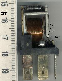
What’s a relay?
I admit, I really just wanted to build my own Blender Defender (I don’t even have a cat!). However, building a 5V controllable outlet can be handy for many applications. For these power hogs, a relay is the perfect fit.
A relay is a large mechanical switch. That switch is toggled on or off by energizing a coil.
In this example we are going to talk about the simplest version of a relay. Inside the relay are two paddles made of metal. One paddle is made of a ferrous material like steel and is free to move. The other paddle is made of copper and stationary. When these paddles touch (the closed switch state), they are capable of allowing a large amount of power to flow – like 30A@120VAC (huge!).
The other half the relay is called the coil. This is basically a small electro-magnet. If you send current through the coil, a magnetic force is created, which pulls on the steel paddle causing it to move (flip) and touch the copper paddle – as if you flipped a light switch. The coil requires a small amount of power (5VDC @ 80mA). So you see, controlling the low-power coil allows us to actually control quite a lot of power!
It is important to note the coil is physically isolated from the paddles. If you have 120VAC running through the paddles, you don’t have to worry about that 120VAC sneaking back into and vaporizing your microcontroller (connected to the coil).
The paddles are capable of carrying very large currents. Both AC or DC – the paddles don’t care. A relay can be used to control a DC motor, or an AC lamp.
The relay that we will be working with, in this tutorial, is a beefcake in my opinion. It can handle a lot of power – 30A at 220VAC. What happens if you violate this limit? I have thankfully never been in that situation. I have heard reports that the relay will begin to heat up. When the voltage/current becomes large enough, there will be sparks inside the relay as you switch the paddles. If these sparks get large enough, you can actually spot weld the movable paddle to stationary paddle causing the relay to fail, potentially in the ‘on’ position. Obviously this would be very bad on many levels.
Like we do with capacitors, we under-rate the relay so that we mitigate the risk of relay failure. If you need 10A@120VAC, don’t use a relay rated for 10A@120VAC, instead use a bigger one (such as 30A@120VAC). Remember, power = current * voltage so a 30A@220V relay can handle up to a 6,000W device (two hair dryers).
The Outlet

All the usual warnings apply: Main voltage (120VAC or 220VAC) can kill you. This project, done incorrectly, could certainly burn down your house. Have your pet spayed or neutered. Shampoo is better. Do not work on or solder to any part of a project while it is plugged into the wall – just unplug it!
You can get the Eagle files for the control board here. The control board is composed of a relay along with a NPN transistor and LED.
What’s a relay?
I admit, I really just wanted to build my own Blender Defender (I don’t even have a cat!). However, building a 5V controllable outlet can be handy for many applications. For these power hogs, a relay is the perfect fit.
A relay is a large mechanical switch. That switch is toggled on or off by energizing a coil.
In this example we are going to talk about the simplest version of a relay. Inside the relay are two paddles made of metal. One paddle is made of a ferrous material like steel and is free to move. The other paddle is made of copper and stationary. When these paddles touch (the closed switch state), they are capable of allowing a large amount of power to flow – like 30A@120VAC (huge!).
The other half the relay is called the coil. This is basically a small electro-magnet. If you send current through the coil, a magnetic force is created, which pulls on the steel paddle causing it to move (flip) and touch the copper paddle – as if you flipped a light switch. The coil requires a small amount of power (5VDC @ 80mA). So you see, controlling the low-power coil allows us to actually control quite a lot of power!
It is important to note the coil is physically isolated from the paddles. If you have 120VAC running through the paddles, you don’t have to worry about that 120VAC sneaking back into and vaporizing your microcontroller (connected to the coil).
The paddles are capable of carrying very large currents. Both AC or DC – the paddles don’t care. A relay can be used to control a DC motor, or an AC lamp.
The relay that we will be working with, in this tutorial, is a beefcake in my opinion. It can handle a lot of power – 30A at 220VAC. What happens if you violate this limit? I have thankfully never been in that situation. I have heard reports that the relay will begin to heat up. When the voltage/current becomes large enough, there will be sparks inside the relay as you switch the paddles. If these sparks get large enough, you can actually spot weld the movable paddle to stationary paddle causing the relay to fail, potentially in the ‘on’ position. Obviously this would be very bad on many levels.
Like we do with capacitors, we under-rate the relay so that we mitigate the risk of relay failure. If you need 10A@120VAC, don’t use a relay rated for 10A@120VAC, instead use a bigger one (such as 30A@120VAC). Remember, power = current * voltage so a 30A@220V relay can handle up to a 6,000W device (two hair dryers).
The Outlet

The goal is the get a GFCI outlet into some sort of a housing, with a power cord, the relay, and control circuitry.
Materials:
Truthfully, the GFCI may only shut off when there is a current leak across a connection to ground – and not an over-current condition. What this means is if your ‘project’ suddenly pulls 50A because the microwave turned on, the GFCI will not trip off. But it you accidentally touch the wrong exposed wire, the GFCI will trip because it will detect a fault to ground (saving your heart from cardiac arrest). We repeat – when working on any part of an AC project, unplug the thing from the wall.
The Inline Power Control Board
The first thing you need to do is build up the Power Control board.

The Build
Take that beautiful extension cord and cut off the female connector about 6" from the female end.

A male US power plug next to the cut off end of the extension cord
Materials:
- GFCI Outlet ($10)
- Nail mount housing ($1)
- Thick 3-wire type extension cord, 8 feet (2-wire cords will not work) ($7)
- Relay ($4)
- Control board and parts ($5)
Truthfully, the GFCI may only shut off when there is a current leak across a connection to ground – and not an over-current condition. What this means is if your ‘project’ suddenly pulls 50A because the microwave turned on, the GFCI will not trip off. But it you accidentally touch the wrong exposed wire, the GFCI will trip because it will detect a fault to ground (saving your heart from cardiac arrest). We repeat – when working on any part of an AC project, unplug the thing from the wall.
The Inline Power Control Board
The first thing you need to do is build up the Power Control board.
This board contains the relay, transistor, and activation LED. The board requires 5V and GND to operate. A control pin controls whether the relay is ‘closed’ (allows high power to flow) or ‘open’ (paddle’s default state of disconnected).
The control board is fairly straight forward. The coil within the relay requires up to 80mA. This is more than a GPIO pin can handle (20mA by default) so we use NPN transistor as a controllable connection to ground. The NPN transistor can handle up to a 200mA which is more than the coil (80mA) and the LED (20mA) combined.
When the ‘RELAY’ pin (aka CTRL) goes high, the NPN transistor connects to ground sending current through the coil (activating the relay) and through the LED (turning the activation LED on). R1 pulls the ‘RELAY’ pin to ground so if anything goes haywire the relay will remain in the safe, off position.
Note: The 1N4148 diode is connected in a odd fashion for a reason. This is placed between power and ground in a reverse fashion. When the coil of the relay is de-activated, it acts like an inductor, trying to suppress current change. This can cause some havoc on the 5V power rail. When this happens, the 1N4148 will forward bias causing the current stored in the coil to flow happily back to the 5V rail protecting the power supply and the near-by parts.
The Build
Take that beautiful extension cord and cut off the female connector about 6" from the female end.

A male US power plug next to the cut off end of the extension cord
This should leave leave a few feet of extension cord between the part that plugs into the wall (male end) and the bare, exposed, recently cut-off end of the extension cord. Don’t plug it in!
Note: A two-wire extension cord will not work correctly. Notice we are using thick, three-wire circular extension cord. This extra wire is the ground return and allows the GFCI to operate correctly.
Using a meter set to continuity, check that the ground pin (the round one) is indeed connected to the green ground wire. I’ve seen a few extension cords with non-standard colors.

Use a wire stripper or an exacto-knife to remove about 6" of the sheath from the extension cord. You should find three wires - black, white and green.


Use wire strippers to strip the three wires individually about 1". I twist the ends of the wires to combine the strands of the wires together in preparation for soldering.


Notice the hooks on the three wires. I wrapped the tinned ends of wire around a small jewelers screw driver to create a half circle within the wire. This will aid connection to the screws on the GFCI.

Sometimes the roll of solder can be used as a third hand.


The goal here is to 'tin' the three wires. Adding solder to each of the stranded wires will hold all the wires together and allow for easier manipulation later.

Be sure to thread the extension cord through the housing (shown above) before soldering to the control board. It's a huge pain to have to cut and remove the wires from the control board.

Be sure to thread the extension cord through the housing (shown above) before soldering to the control board. It's a huge pain to have to cut and remove the wires from the control board.

Be sure the extension is threaded through the housing before you do this step.
With a good 6" of wire exposed, cut the black wire about 5" down from the end. The is where the relay will live.
With a good 6" of wire exposed, cut the black wire about 5" down from the end. The is where the relay will live.

Notice the hooks on the three wires. I wrapped the tinned ends of wire around a small jewelers screw driver to create a half circle within the wire. This will aid connection to the screws on the GFCI.
Here we have the black wire cut and soldered to the control board. The relay is a NO (Normally Open) type relay. When power is off, there is no connection between the two thick black strands that you just cut and soldered. This is a safety feature - if all things go wrong and the power goes out of the coil, the relay will kick off and the outlet will shut down.
Conversely, when you send 5V to the coil, the paddle flips from the 'off' state to the 'on' state, connecting the two pieces of black wire (on the left side of the picture above), power is delivered to the outlet and your project is powered.

Now we connect the wires from the extension cord to the outlet. The Black and white wires connect to the two side terminals of the GFCI - the green wire (ground) connects to the end of the outlet.
Advanced trick: Notice how the hooks of the tinned wires are arranged so that they are clock-wise. If you align the hooks of the wires under the screws correctly, as you tighten the screws, the hook of the wire will be 'sucked' into the tightening screw. This creates a very compact connection.

Now lower the relay into the enclosure and feed the control wires (red, yellow, and black) out one corner of the housing. (You're right, the extension cord wires are not soldered to the relay board in this picture - please make believe).

You can double-stick tape the control board to the bottom of the housing or just let it float - the wires from the extension cord will tend to hold it in place. Once you have everything lowered into place, screw the outlet onto the enclosure, and the face plate onto the enclosure.

Here we test the controllable outlet against the Boxing Timer

Here we test the controllable outlet against the Boxing Timer
DO NOT plug the extension cord into the wall yet.
Now for the moment of truth. Attach the three control wires (5V, GND, and CTRL) to some sort of system. In the above picture, I have a fairly dirty breadboard. All that I am actually using on the bread board is 5V and GND - ignore all the other parts as they are not doing anything. I then manually toggled the control wire from GND (off) to 5V (on). You can do the same thing by plugging into the 5V and GND pins on an Arduino board.
Tying the CTRL line to 5V I heard a very friendly click as the relay kicked over. This indicated (along with the LED on the control board) that the relay was actuated to the 'on' position. Removing CTRL from the 5V rail (called floating because the CTRL line is neither connected to 5V or GND), the relay released. This is good! If CTRL is left floating or tied to ground, the outlet is turned off.
You can also use a meter in continuity mode to check that the relay is working properly before youconnect to 120VAC. When the relay’s open, one of the fins of the plug and one of the rectangular holes of the outlet will not have continuity, and when it’s closed, they will. The other fin and rectangular hole will always have continuity, as will the ground pin and the funny hole. I always do this check before plugging into the 120VAC, because I am, you know, paranoid.
The next step is to plug the extension cord into the wall and test again. If anything goes wrong the GFCI should activate and cut off. Be sure to unplug the outlet anytime you are working on it. Please don’t get zapped!
You should now have an outlet that is fully controllable over 5V logic. When you plug a device into the outlet, it will by default be off. When you expose 5V to the CTRL line, the relay will activate turning on power to the device plugged into the outlet.
No hay comentarios:
Publicar un comentario